Precautions Précautions
Precauciones
Vorsichtsmaßnahmen Precauzioni Försiktighetsåtgärde
CTA-1505R/CTA-1502R
FM/MW/LW/RDS Digital Commander/Receiver
English
GUIDE FOR INSTALLATION AND CONNEC-
TIONS
Please read this GUIDE thoroughly before
starting the installation and connections.
In case of problems when installing your unit,
please contact your authorized ALPINE deal-
er.
Français
Español Deutsch Italiano
Svenska
GUIA DE INSTALACION Y CONEXIONES
Antes de realizar la instalación y las conexio-
nes, lea cuidadosamente esta GUÍA.
En caso de presentarse algún problema du-
rante la instalación CTA-1505R/CTA-1502R,
tome contacto con su distribuidor autorizado
ALPINE.
GUIDE D’INSTALLATION ET DE CON-
NEXIONS
Veuillez lire attentivement le GUIDE avant
d’installer et de raccorder l’appareil.
En cas de problèmes lors de l’installation de
l’unité, prière de contacter le revendeur agréé
d’ALPINE.
GUIDA ALL’INSTALLAZIONE ED AI COLLE-
GAMENTI
Leggere questa GUIDA con attenzione prima
di iniziare l’installazione ed i collegamenti.
In caso di problemi quando si installa la unitá,
rivolgersi al proprio rivenditore autorizzato
ALPINE.
INSTALLATIONS-OCH ANSLUTNINGSAN-
VISNING
Läs noga igenom denna bruksanvisning före
installations-och anslutningsstart.
Kontakta din auktoriserade ALPINE återför-
säljare om det uppstår problem vid installa-
tionen av apparaten.
68P11199Y27-A
Printed in Korea (Y)
HINWEISE ÜBER DIE INSTALLATION UND
ANSCHLÜSSE
Lesen Sie diese HINWEISE bitte aufmerksam
durch, bevor Sie mit der Installation und den
Anschlüssen beginnen.
Sollten beim Einbau des CTA-1505R/CTA-1502R
Probleme auftreten, so wenden Sie sich bitte
an einen von ALPINE autorisierten Fachhänd-
ler.
’ Be sure to disconnect the negative cable from the
(–) pole of the battery before connecting your
CTA-1505R/CTA-1502R to avoid short circuits.
’ Use the correct ampere rating when replacing fuses.
Failure to do so may result in fire or electric shock.
’ Be sure to connect the leads correctly according to
the diagram. Otherwise malfunctioning of the unit
and/or damage to the vehicle may occur.
’ Be sure to connect the speaker (–) leads to the
speaker (–) terminal. Never connect left and right
channel speaker cables to each other or to the
vehicle body.
’ Use only vehicles with a 12 volt negative (–) ground.
Check with your dealer if you are not sure. Failure to
do so may result in fire or electric shock.
’ You must be very careful when connecting wires to
the vehicle’s electrical system. Be sure you do not
use leads of factory installed components (like an
on-board computer). When connecting CTA-1505R/
CTA-1502R to the fuse box, make sure the fuse for
the intended circuit of the CTA-1505R/CTA-1502R
has the appropriate amperage. Failure to do so may
result in damage to the unit and/or the vehicle.
When in doubt, consult your ALPINE dealer.
’ The CTA-1505R/CTA-1502R uses female RCA-type
jacks for connection to other units (e.g. amplifier)
having RCA connections. You may need an adaptor
to connect other units. If so, please contact your
authorized ALPINE dealer for assistance.
’ S’assurer de déconnecter le câble négatif du
pôle (–) de la batterie avant de connecter le
CTA-1505R/CTA-1502R pour éviter des court-
circuits.
’ Utilisez des fusubles de l’amperage approprie. Si-
non il y a risque d’incendie ou de choc électrique.
’ S’assurer de connecter correctement les conduc-
teurs à code de couleur selon le schéma. Sinon
l’unité peut mal fonctionner et/ou le véhicule peut
être endommagé.
’ S’assurer de connecter les câbles d’enceinte (–) à la
borne d’enceinte (–). Ne jamais connecter les câ-
bles d’enceinte du canal gauche et droit l’un à
l’autre ou à la carrosserie du véhicule.
’ Utiliser le systeme uniquement dans des voitures
ayant une masse negative (–) de 12 volts. Vérifier
avec votre revendeur en cas de doute. Le non-
respect de cette précaution risque de provoquer un
incendie ou un choc électrique.
’ Il faut faire très attention lors de la connexion des
câbles au système électrique du véhicule. S’assu-
rer de ne pas utiliser des conducteurs de composants
installés en usine (tel qu’un ordinateur de bord).
Lors de la connexion de l’unité au boîtier à fusible,
s’assurer que le fusible du circuit désigné pour l’unité
a l’ampérage approprié. Sinon, l’unité et/ou le véhi-
cule peuvent être endommagés. En cas de doute,
consulter le revendeur ALPINE.
’ Le CTA-1505R/CTA-1502R utilise des prises femel-
les de type RCA pour le raccordement à d’autres
appareils (tels qu’un amplificateur), munis de
connecteurs RCA. Il se peut que vous ayez à utiliser
un adaptateur pour raccorder d’autres appareils.
Dans ce cas, veuillez vous adresser à un conces-
sionnaire ALPINE agréé pour vous aider dans votre
choix.
’ A fin de evitar cortocircuitos, asegúrese de desco-
nectar el cable negativo del polo (–) de la batería
antes de conectar el CTA-1505R/CTA-1502R.
’ Utilice el amperaje correcto cuando cambie fusibles.
De lo contrario, podrá ocasionar un incendio o
descarga eléctrica.
’ Asegúrese de conectar correctamente los cables
difereciados por colores, siguiendo las indicaciones
del diagrama. De no hacerlo, la unidad podrá fun-
cionar incorrectamente y/o el vehículo podrá sufrir
daños.
’ Asegúrese de conectar los cables negativos (–) de
altavoces al terminal de altavoces (–). Nunca conec-
te los cables de altavoces de los canales derecho e
izquierdo uno a otro, ni tampoco a la carrocería del
vehículo.
’ Utilice el sistema solamente en vehiculos que ten-
gan una puesta a tierra negativa (–) de 12 volts.
Verifique con su distribuidor en caso de duda. De lo
contrario, podrá ocasionar un incendio o descarga
eléctrica.
’ Usted deberá tener mucho cuidado durante la co-
nexión de cables al sistema eléctrico del vehículo.
Asegúrese de no utilizar los conductores de compo-
nentes que vengan instalados de fábrica (como un
computador incorporado, por ejemplo). Al conectar
la unidad a la caja de fusibles, asegúrese de que el
fusible designado para el circuito de la unidad sea
del amperaje adecuado. De lo contrario, la unidad y/
o el vehículo podrán sufrir daños. Cuando tenga
dudas, consulte a su distribuidor ALPINE.
’ El CTA-1505R/CTA-1502R utiliza tomas RCA hem-
bra para la conexión a otras unidades (p. ej. un
amplificador) que posea tomas RCA. Es posible que
usted necesite un adaptador para conectar otras
unidades. En tal caso, póngase en contacto con su
proveedor ALPINE para solicitarle ayuda.
’ Damit beim Anschluß keine Kurzschlüsse auftre-
ten können, vor Beginn der Einbauarbeiten das
Massekabel vom Minuspol (–) der Batterie ab-
klemmen.
’ Sicherungen nur durch solche mit der richtigen
Amperezahl ersetzen. Nichtbeachtung dieses Punk-
tes kann einen Brand und/oder elektrischen Schlag
zur Folge haben.
’ Auf korrekten Anschluß der farbcodierten Kabel
achten! Anschlußfehler können Betriebsstörungen
des Geräts bzw. Fahrzeuges zur Folge haben.
’ Die Minusadern (–) der Lautsprecherkabel an Minus-
klemmen (–) anschließen! Die Minusadern für
rechten und linken Kanal dürfen nicht zusammen-
geschlossen oder an der Karosserie an Masse
gelegt werden.
’ Nur in fahrzeugen mit 12-V-Bordnetz und minus
(–) an Masse verwenden. Fragen Sie im Zweifelsfall
Ihren Händler. Nichtbeachtung dieses Punktes kann
einen Brand und/oder elektrischen Schlag zur Folge
haben.
’ Beim Anschluß an das Kfz-Bordnetz vorsichtig
vorgehen! Das Gerät nicht an Kabel anschließen,
die anderen Fahrzeugsystemen vorbehalten sind
(z. B. Bordcomputer u. dgl.). Beim Anschluß im
Sicherungskasten darauf achten, daß die Sicherung
des gewählten Stromkreises die für das Geräts
vorgeschriebene Amperezahl aufweist. Bei
Nichtbeachtung dieses Punkts sind Folgeschäden
am Gerät bzw. am Fahrzeug nicht ausgeschlossen.
Im Zweifelsfall gibt Ihr ALPINE-Fachhändler gerne
Auskunft.
’ Der CTA-1505R/CTA-1502R ist mit Cinchbuchsen
ausgestattet, die den Anschluß an andere Geräte
mit entsprechenden Buchsen (z.B. Verstärker) er-
möglichen. Zum Anschließen eines anderen Geräts
werden unter Umständen Steckeradapter benö-
tigt. Lassen Sie sich diesbezüglich von Ihrem
Alpine-Händler beraten.
’ Assicurarsi di scollegare il cavo negativo dal polo
negativo (–) della batteria prima di collegare il lettorè
CTA-1505R/CTA-1502R per evitare corto circuiti.
’ Usare fusubili di ricambio dell’amperaggio corret-
to. Altrimenti ne possono risultare incendi o scosse
elettriche.
’ Assicurarsi di collegare i fili codificati in base al
colore nel modo corretto secondo il diagramma.
Altrimenti, possono verificarsi malfunzionamenti o
danni all’ apparecchio o all’ auto.
’ Assicurarsi di collegare i fili negativi degli altopar-
lanti (–) al terminale (–). Non collegare mai i cavi
destro e sinistro degli altoparlanti l’uno con l’altro o
all chassis dell’automobile.
’ Usare solo in veicoli con batteria da 12 volt a massa
negativa (–). Controllare con il concessionario se
non si è sicuri. Altrimenti ne possono risultare in-
cendi o scosse elettriche.
’ Fare molta attenzione quando si collega i fili con il
sistema elettrico del veicolo. Assicurarsi di non
usare i fili dei componenti installati in fabbrica (ad
esempio un computer fisso). Quando si collega la
unitá con la scatola dei fusibili, assicuratevi assicu-
rarsi che il fusibile per il circuito del lettore della
unitá sia del corretto amperaggio. In caso contrario
possono verificarsi malfunzionamenti o danni all’
apparecchio o all’ auto.
In caso di dubbi, rivolgersi al proprio rivenditore
ALPINE.
’ Il CTA-1505R/CTA-1502R impiega prese femmina di
tipo RCA per il collegamento ad altri apparecchi
(p.es. amplificatore) con collegamenti RCA. Puö
essere necessario un adattatore per il collegamento
ad altri apparecchi. In questo caso rivolgersi per
assistenza al proprio rivenditore autorizzato ALPI-
NE.
’ Koppla loss bilbatteriets negativa kabel (–) innan
du påbörjar anslutningen av CTA-1505R/CTA-1502R.
I annat fall kan kortslutning uppstå.
’ Använd korrekt amperetal vid byte av säkringar. Fel
amperetal kan orsaka brand eller elektriska stötar.
’ Anslut alla färgkodade kablar rätt enligt anslutnings-
schemat. Fel anslutningar kan orsaka felfunktion
och/eller skada på apparaten eller bilen.
’ Anslut negativa (–) högtalarkablar till (–) anslutninga-
rna. Höger och vänster kablar får inte anslutas till
varandra eller till bilkarossen.
’ Avsedd endast för montering i bilar med 12 volts,
negativt (–) jordat batteri. Rådfråga återförsäljaren
i osäkra fall. Fel amperetal kan orsaka brand eller
elektriska stötar.
’ Var mycket försiktig vid anslutning av kablarna till
bilens elektriska system. Anslut inte till kablarna för
fabriksmonterad utrustning (t.ex. en färddator). Vid
anslutning av apparaten till säkringslådan måste
du se till att säkringen i kretsen apparaten ansluts
till har tillräckligt stor amperekapacitet. I annat fall
kan skada uppstå på apparaten och/eller bilen.
Kontakta din ALPINE-återförsäljare om du känner
dig osäker.
’ CTA-1505R/CTA-1502R använder sig av RCA-
kopplingar med honkontakt för anslutning till andra
komponenter (t.ex. förstärkare) med RCA-
kopplingar. Det kan hända att en adapter behövs
för anslutning till andra komponenter. Kontakta i så
fall en auktoriserad ALPINE-handlare för ytterligare
råd.
IMPORTANT
Enregistrer le numéro de série de l’appareil
dans l’espace prévu au dos de ce manuel et
le conserver en permanence. La plaque de
numéro de série est située au fond de l’ap-
pareil.
WICHTIG!
Tragen Sie die Seriennummer des Geräts
bitte für alle Fälle in das hierfür vorgesehe-
ne Feld auf der hinteren Umschlagseite der
Bedienungsanleitung ein. Das Serien-
nummernschild befindet sich an der
Geräteunterseite.
IMPORTANTE
Anote el número de serie de su unidad en el
espacio proporcionado en la cubierta poste-
rior de este manual, y consérvelo como un
registro permanente. La placa con el núme-
ro de serie está ubicada en la parte inferior
de la unidad.
IMPORTANT
Please record the serial number of your
unit in the space provided on the back
cover of Owner‘s Manual and keep it as a
permanent record. The serial number plate
is located on the bottom of the unit.
IMPORTANTE
Segnare il numero di serie del vostro appa-
recchio sullo spazio fornito sul retro della
copertina di questo libretto delle istruzioni e
conservarlo per rifermenti futuri. La piastri-
na indicante il numero di serie è collocata
sul fondo dell’apparecchio.
VIKTIGT
Anteckna apparatens serienummer i utrym-
met på bruksanvisningens baksida. Behåll
bruksanvisningen hemma för framtida refe-
rens. Serienumret finns utsatt på apparatens
undersida.
Installation Installation
Instalación
Einbau Installazione Installation
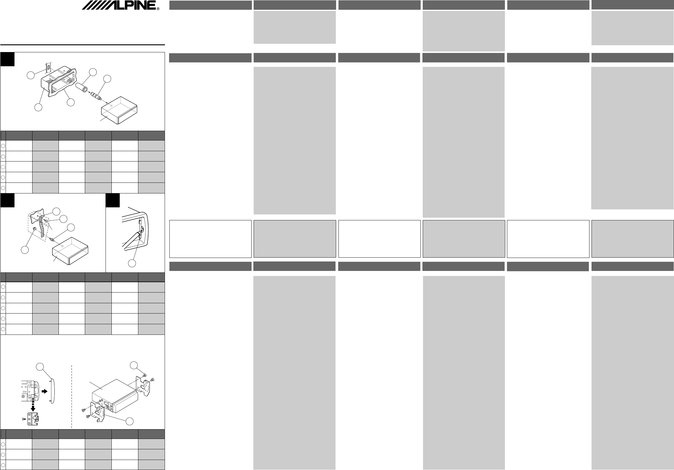
a Enlevez la façade détachable (voir page 12 du
mode d’emploi). Enlevez l‘attache de montage
de l’appareil (voir la procédure de retrait
ci-dessous). Poussez l‘attache de montage dans
le tableau de bord.
s Si votre véhicule possède une Applique, instal-
lez le long boulon à tête hexagonale sur le
panneau arrière du CTA-1505R/CTA-1502R et
placez le bouchon caoutchouté sur le boulon à
tête hexagonale. Si le véhicule ne possède pas
de Support de montage, renforcez l’unité avec la
bande de montage métallique fournie. Raccor-
dez tous les fils du CTA-1505R/CTA-1502R de la
manière décrite dans la section “CONNEXIONS”.
Remarque:
Sur la vis ≤, se procurer une vis appropriée à
l’emplacement d’installation du châssis.
d Glissez le CTA-1505R/CTA-1502R dans le tableau
de bord. Quand l’appareil est installé, vérifiez
que les goupilles de blocage sont parfaitement
posées à la position abaissée. Ceci s’obtient en
appuyant fermement sur l’appareil tout en abais-
sant la goupille de blocage à l’aide d’un petit
tournevis. De cette façon, l’appareil sera
convenablement verrouillé et il ne risquera pas
de tomber accidentellement du tableau de bord.
Installez enfin le panneau avant amovible.
Dépose
1. Déposer le panneau avant amovible.
2. Utiliser un petit tournevis (ou objet similaire) pour
soulever les vis vers le haut (voir Fig.d). Chaque
fois qu’une vis est débloquée vers le haut, tirer
légèrement sur l’appareil pour qu’il ne se rebloque
pas avant de dévisser la vis suivante.
3. Extraire l’appareil, en le maintenant déverrouillé.
a Remove the Detachable Front Panel (refer to page
12 of Owner‘s Manual). Slide mounting sleeve
from main unit (see Removal Procedure below).
Slide the mounting sleeve into the dashboard.
s When your vehicle has the Bracket, mount the
long hex bolt onto the rear panel of the CTA-
1505R/CTA-1502R and put the Rubber Cap on the
hex bolt. If your vehicle does not have the Mount-
ing Support, reinforce the head unit with the
metal mounting strap supplied. Connect all the
leads of the CTA-1505R/CTA-1502R according to
details described in the CONNECTIONS section.
NOTE:
For the screw ≤, provide a proper screw to the
chassis installing location.
d Slide the CTA-1505R/CTA-1502R into the dash-
board. When the unit is in place, make sure the
locking pins are fully seated in the down position.
This can be done by pressing firmly in on the unit
while pushing the locking pin down with a small
screwdriver. This ensures that the unit is properly
locked and will not accidentally come out from the
dashboard. Install the Detachable Front Panel.
Removal
1. Remove the detachable front panel.
2. Use a small screwdriver (or similar tool) to push the
locking pins to the ”up” position (see Fig.d). As
each pin is unlocked, gently pull out on the unit to
make sure it does not re-lock before unlocking the
second pin.
3. Pull the unit out, keeping it unlocked as you do so.
a Extraiga el panel extraíble frontal (consulte la
pàgina 12 del maual de instrucciones). Deslice el
manguito de montaje desde la unidad principal
(vea el procedimiento de extracción de abajo).
Deslice el manguito de montaje al tablero de
instrumentos.
s Si su vehículo posee soporte, instale el perno
hexagonal largo en el panel posterior del CTA-
1505R/CTA-1502R y coloque el tapón de caucho
sobre dicho perno. Si su vehículo no posee sopor-
te de montaje, refuerce la unidad principal con la
banda metálica de montaje suministrada. Conec-
te todos los conductores del CTA-1505R/
CTA-1502R de acuerdo con los detalles descritos
en la sección CONEXIONES.
Nota:
A propósito del tornillo ≤, prepare un tornillo
apropiado al lugar de instalación del chasis.
d Deslice el CTA-1505R/CTA-1502R dentro del pa-
nel de instrumentos. Cuando la unidad esté en su
lugar, cerciórese de que los pasadores hayan
quedado completamente asentados hacia adajo.
Esto podrá realizarse empujando firmemente la
unidad manteniendo presionado el pasador de
bloqueo hacia abajo con un destornillador peque-
ño. Esto asegurará el que la unidad quede
adecuadamente bloqueada y que no se salga
accidentalmente del panel de instrumentos. Ins-
tale el panel frontal desmontable.
Extracción
1. Retire el panel delantero desmontable.
2. Utilice un pequeño destornillador (u otra herramien-
ta similar) para empujar los pasadores de fijación
(consulte la Fig.d). Cuando desbloquee un pasador,
tire suavemente de la unidad hacia afuera para ase-
gurarse de que no se vuelva a bloquear antes de
desbloquear el otro.
3. Tire la unidad hacia fuera, manteniéndola destrabada
mientras lo hace.
a Nehmen Sie das Bedienteil vom Gerät ab (siehe
Seite 12 der Bedienungsanleitung). Ziehen Sie
den Einbaurahmen vom Hauptgerät ab (siehe
“Ausbau” weiter unten). Schieben Sie den Ein-
baurahmen dann in das Armaturenbrett.
s Falls Ihr Fahrzeug mit einer Stützhalterung
versehen ist, drehen Sie die lange Sechskant-
schraube in die Rückseite des CTA-1505R/CTA-
1502R und stecken danach die Gummikappe
auf den Schraubenkopf. Sollte keine Stützhal-
terung vorhanden sein, muß das Gerät mit
Hilfe der mitgelieferten Stützleiste fixiert wer-
den. Schließen Sie die Kabel des CTA-1505R/
CTA-1502R gemäß den Anweisungen im Ab-
schnitt ANSCHLÜSSE an.
HINWEIS:
Als Schraube ≤ verwenden Sie eine geeigne-
te Schraube für die Chassis-Gehäusebefesti-
gung.
d Schieben Sie das CTA-1505R/CTA-1502R bis zum
Anschlag in das Armaturenbrett. Vergewissern
Sie sich, daß die Verriegelungsstifte gut einra-
sten. Schieben Sie das Gerät hierzu fest in das
Armaturenbrett, und drücken Sie die Verriege-
lungsstifte dabei mit einem kleinen Schrau-
bendreher nach unten. Der Rastmechanismus
sorgt für einen wackelfreien Sitz und verhütet,
daß das Gerät aus Versehen aus dem Armatu-
renbrett gezogen wird. Bringen Sie danach das
Bedienteil wieder an.
Ausbau
1. Nehmen Sie das Bedienteil vom Gerät ab.
2. Drücken Sie die Verriegelungsstifte mit einem klei-
nen Schraubendreher (oder einem ähnlichen
Werkzeug) hoch (siehe Abb.d). Nach dem Lösen
der ersten Verriegelung ziehen Sie das Gerät ein
wenig heraus, so daß der Stift beim Lösen der zwei-
ten Verriegelung nicht wieder eingreifen kann.
3. Ziehen Sie das Gerät mit gelösten Verriegelungs-
stiften aus dem Einbaurahmen.
a Rimuovere il pannello anteriore estraibile (fare
riferimento a pagina 12 del manuale di istruzioni).
Sfilare l’apparecchio principale dal manicotto di
montaggio (vedere “Procedimento di rimozione”
sotto). Far scorrere il manicotto di montaggio
dentro il cruscotto.
s Quando il veicolo è dotato di staffa, montare il
lungo bullone esagonale sul pannello posteriore
del CTA-1505R/CTA-1502R e applicare il cappuc-
cio di gomma al bullone esagonale. Se il veicolo
non ha il supporto di montaggio, rinforzare l’ap-
parecchio principale con la cinghia di montaggio
metallica in dotazione. Collegare tutti i cavi del
CTA-1505R/CTA-1502R secondo i dettagli descrit-
ti nella sezione COLLEGAMENTI.
NOTA:
Per la vite ≤, provvederai di una vite adatta al
vano di installazione dello chassis.
d Far entrare il CTA-1505R/CTA-1502R il più possi-
bile nella plancia di montaggio. Quando l’appa-
recchio è inserito, verificare che i perni di blocco
siano ben assestati nella posizione abbassata.
Questo può essere ottenuto premendo ferma-
mente sull’apparecchio mentre si spinge in giù il
perno con un piccolo cacciavite. Questo assicura
che l’apparecchio sia correttamente bloccato e
non fuoriesca accidentalmente dal cruscotto. In-
stallare il pannello anteriore staccabile.
Rimozione
1. Rimuovere il pannello anteriore estraibile.
2. Usare un piccolo cacciavite (o un oggetto simile)
per spingere i perni di blocco nella posizione solle-
vata (vedere la fig.d). Dopo avere sbloccato un
perno, alzare delicatamente l’apparecchio per con-
trollare
che non si riblocchi prima di sbloccare il
secondo perno.
3.
Estrarre l’apparecchio assicurandosi che sia sblocca-
to.
a Ta loss den löstagbara frontpanelen (vi hänvisar
till sid. 12 i bruksanvisningen). Dra loss monte-
ringskassetten från själva bilstereon (vi hänvisar
till tillvägagångssättet vid löstagning nedan).
Skjut in monteringskassetten i instrumentinfatt-
ningen.
s När fordonet har en hållare: fäst den långa, sex-
kantiga bulten på baksidan av CTA-1505R/CTA-
1502R och sätt på gummihatten på den sexkan-
tiga bulten. När fordonet inte har något monte-
ringsstöd: förstärk själva bilstereon med det
medföljande monteringsbandet av metall. An-
slut samtliga kablar till CTA-1505R/CTA-1502R
enligt anvisningarna i kapitlet ANSLUTNINGAR.
OBS!
Använd en lämplig skruv för kassettens monte-
ringsläge som skruven ≤.
d Skjut in CTA-1505R/CTA-1502R så långt det går i
instrumentinfattningen. Kontrollera efter bilste-
reons montering att låstapparna skjutits ned så
långt det går. Detta kan göras genom att trycka
bilstereon ordentligt inåt, samtidigt som låstap-
pen trycks ned med en liten skruvmejsel. Detta
garanterar att bilstereon fästs ordentligt och inte
kan lossna från instrumentinfattningen av miss-
tag. Fäst den löstagbara frampanelen.
Löstagning
1. Ta loss den löstagbara frontpanelen.
2. Använd en liten skruvmejsel (eller ett liknande verk-
tyg) för att skjuta låstapparna upp (ill.d). Dra
försiktigt bilstereon något utåt efter att låstappen
osäkrats för att vara säker på att bilstereon inte
låses fast igen innan den andra låstappen osäkrats.
3. Dra ut apparaten och se till att den inte är säkrad
när detta görs.
(RCS PONTOISE B 338 101 280)
Je Il Moon Hwa Co.
23-5, 1 Ga, Pil-dong, Jung-gu, Seoul, Korea
CTA-1505R/CTA-1502R
CTA-1505R/CTA-1502R
1
2
3
4
5
6
7
8
9
Front frame
Mounting Bracket
Screws (M5x8)
(Included)
JAPANESE CAR/VOITURE JAPONAISE/
VEHÍCULO JAPONÉS/JAPANISCHES FAHRZEUG/
AUTOMOBILE GIAPPONESE/JAPANSK BIL
1
2
3
Metal Mounting
Strap (Included)
Screw
Bolt Stud (Included)
Hex Nut (M5)
(Included)
Lock Pin
Attache de montage
en métal (Fournie)
Abrazadera metálica
de montaje (Incluído)
Befestigungsstrebe
(Beiliegend)
Copertura di montaggio
in metallo (In dotazione)
Metallbygel
(Medföljer)
Vis Tornillo Schraube Vite
Skruv
Perno (Incluído)
Stiftschraube
(Beiliegend)
Vite prigioniera
(In dotazione)
Pinnbult (Medföljer)
Filetage de boulon
(Fournie)
Ecrou à six pans
(M5) (Fournie)
@
Tuerca hexagonal
(M5) (Incluído)
Sechskantmutter
(M5) (Beiliegend)
Dado esagonale
(M5) (In dotazione)
Sexkantmutter
(M5) (Medföljer)
Tige de
verrouillage
Pasador Verriegelungsstift Perno di blocco
Lasflikar
Bracket
Rubber Cap
(Included)
Hex Bolt (Included)
Dashboard
Support Soporte Stützhalterung Supporto Hållare
Capuchon de caout-
chouc (Fournie)
Tapón de caucho
(Incluído)
Gummikappe
(Beiliegend)
Gummihatt
(Medföljer)
Cappuccio di gom-
ma (In dotazione)
Boulon à six pans
(Fournie)
Perno hexagonal
(Incluído)
Sechskant Stiftsch-
raube (Beiliegend)
Bullone esagonale
(In dotazione)
Sexkantig bult
(Medföljer)
Tableau de bord
Tablero de
instrumentos
Armaturenbrett Cruscotto Instrumentbräda
Mounting Sleeve
(Included)
Gaine de montage
(Fournie)
Manguito de
montaje (Incluído)
Einbaurahmen
(Beiliegend)
Copertura di montag-
gio (In dotazione)
Monteringskassett
(Medföljer)
Cadre de panneau
avant
@
Marco Frontal
@
Frontrahmen Cornice frontalino Inramning
Vis (M5 x 8)
(Fournie)
Viti (M5x8)
(In dotazione)
Skruvar (M5x8)
(Medföljer)
Schrauben (M5 x 8)
(Beiliegend)
Tornillos (M5x8)
(Incluído)
Soporte de
montaje
Applique de
montage
Einbauhalterung
Staffa di
montaggio
Monteringshållare
English Français Español Deutsch Italiano Svenska
English Français Español Deutsch Italiano Svenska
English Français Español Deutsch Italiano Svenska
1
2
5
3
4
6
9
10
7
8
11
12
13
10
CTA-1505R/CTA-1502R
11
12
13


 (8 pages)
 (19 pages)
 (2 pages)
 (36 pages)
 (21 pages)
 Manymanuals.com
 Manymanuals.de
 Manymanuals.fr
 Manymanuals.it
 Manymanuals.pl
 Manymanuals.cz
 Manymanuals.es
 Manymanuals-pt.com
Comments to this Manuals